Overclocking The Bitcoin ASICMiner Blade V2 (Green Board) to ~13.2GH in 30 Minutes or Less
Many of you probably have recently purchased an ASICMiner Blade V2 10.7GH and have been wondering what the easiest way to over clock it might be. I have spent a bit of time working on a solution that would be easy to do with basic soldering skills and tools. One drawback of earlier overclock kits was the need for a hot air station to remove the stock 12mhz oscillator. With this method it is no longer necessary to remove the stock oscillator with a hot air station. The new oscillator is simply placed on the un-populated pads and enabled for a higher hash rate.
What you will need:
A basic soldering Iron, some thin solder and braided desoldering wick. I have added Radio Shack links below for reference or examples, but these items can be sourced from anywhere you want. These can also be found on eBay if you don't want to leave the house.
- Soldering Iron
- Desoldering Braid
- Rosin Core Solder (.032 or smaller)
- Solder Paste
- Magnification Visor
I would suggest watching some videos and tutorials on surface mount soldering and desoldering if you haven't had much experience with with SMD devices.
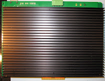
The parts kit includes the eight replacement resistors, a new oscillator (the silver rectangle) and a replacement 15A blade fuse. Self adhesive ASIC chip side heatsinks are optional, but strongly recommended if you are running these on a backplane close together. If you only have a few blades and you can get a lot of airflow directly on the main heatsink, then you may not need the chip side heatsinks. These parts kit is available here.
The Parts

 |
| Optional Heatsink Set |
 |
| Heatsinks With Thermal Conductive Adhesive Installed |
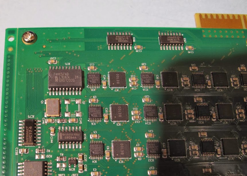
Step One: Disabling the Stock Oscillator
Locate the stock oscillator on the board. It's in the top left hand corner of the board if you are looking at it with the Blade edge connector at the top

Step Two: Adding the overclock oscillator.
Once the stock oscillator has been disabled, apply a small amount of solder paste (if you have it) to the four pads. And place the new 14.745 mhz oscillator with the numbers in the same direction as the 12.0 mhz unit as shown above. While putting pressure on the top of the oscillator with tweezers or a small screwdriver, touch the iron to each pad until the solder flows underneath the pad until all pads are soldered and the unit is firmly in place. Check your work under magnification.
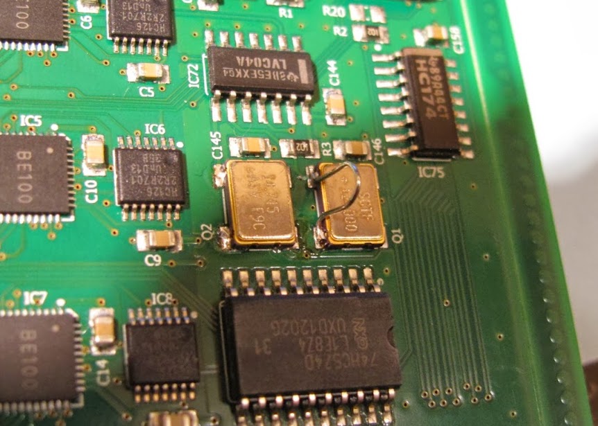 |
| The New Oscillator Soldered In Place |
Step Three: Replacing the R29 (and its 7 sister resistors)
Eight rows of four ASIC chips on the board are powered by their own voltage rail. The stock rail is set at ~1.02V via a resistor divider on each voltage regulator at the top of the board. In this case, we are increasing the rail voltage to 1.25V to support the higher clock speed. This means replacing eight 68.1K resistors at the top of the board labeled 6812 (R29, R41, R53, R65, R77, R89, R101, R113). Watch the videos I linked above to get an idea of how to de-solder and re-solder the new 120K resistors into place. Check your work under magnification unless you have really good eyes.
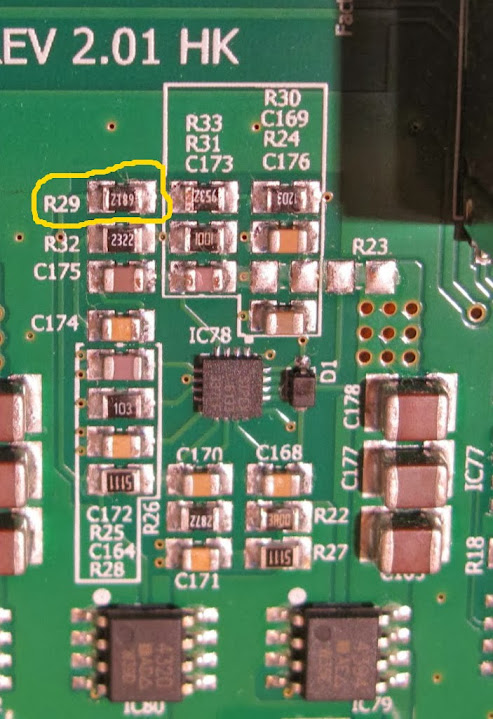 |
| R29 68.1K Resistor Needs To Be Replaced With a 120K |
 |
| Replace R41 |
 |
| Replace R53 |
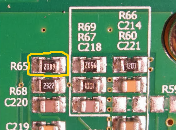 |
| Replace R65 |
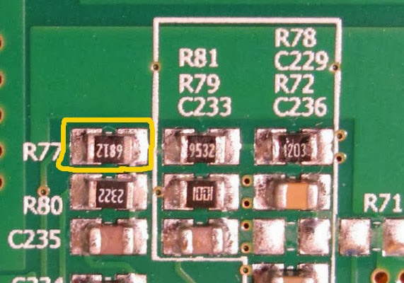 |
| Replace R77 |
 |
| Replace R89 |
 |
| Replace R101 |
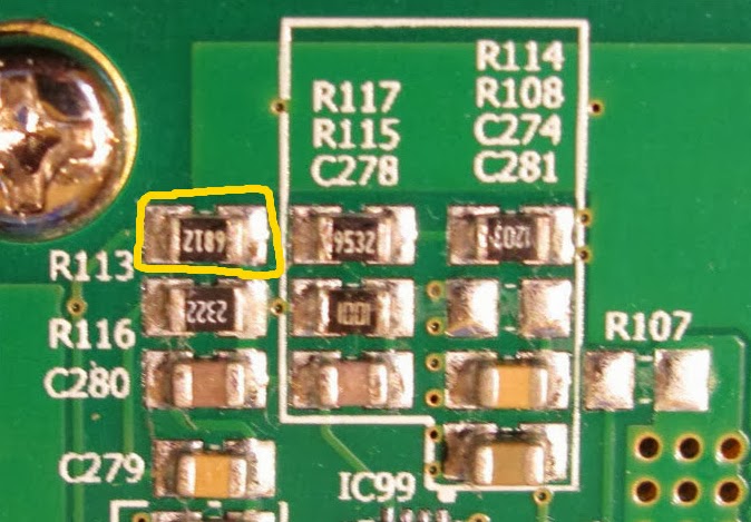 |
| Replace R113 It's ususlly easier to temporarily remove the adjacent heatsink screw |
Step Four: Replacing the 10A with a 15A fuse.
With the increased clock speed and rail voltage comes increased power demand. In this configuration the blade pulls in the neighborhood of 12 amps. The 10A fuse will eventually blow, so change it now.
Begin my desoldering the stock fuse located near the green connector labeled with an "R"
 |
| Remove this fuse |
 |
| Fuse removed |
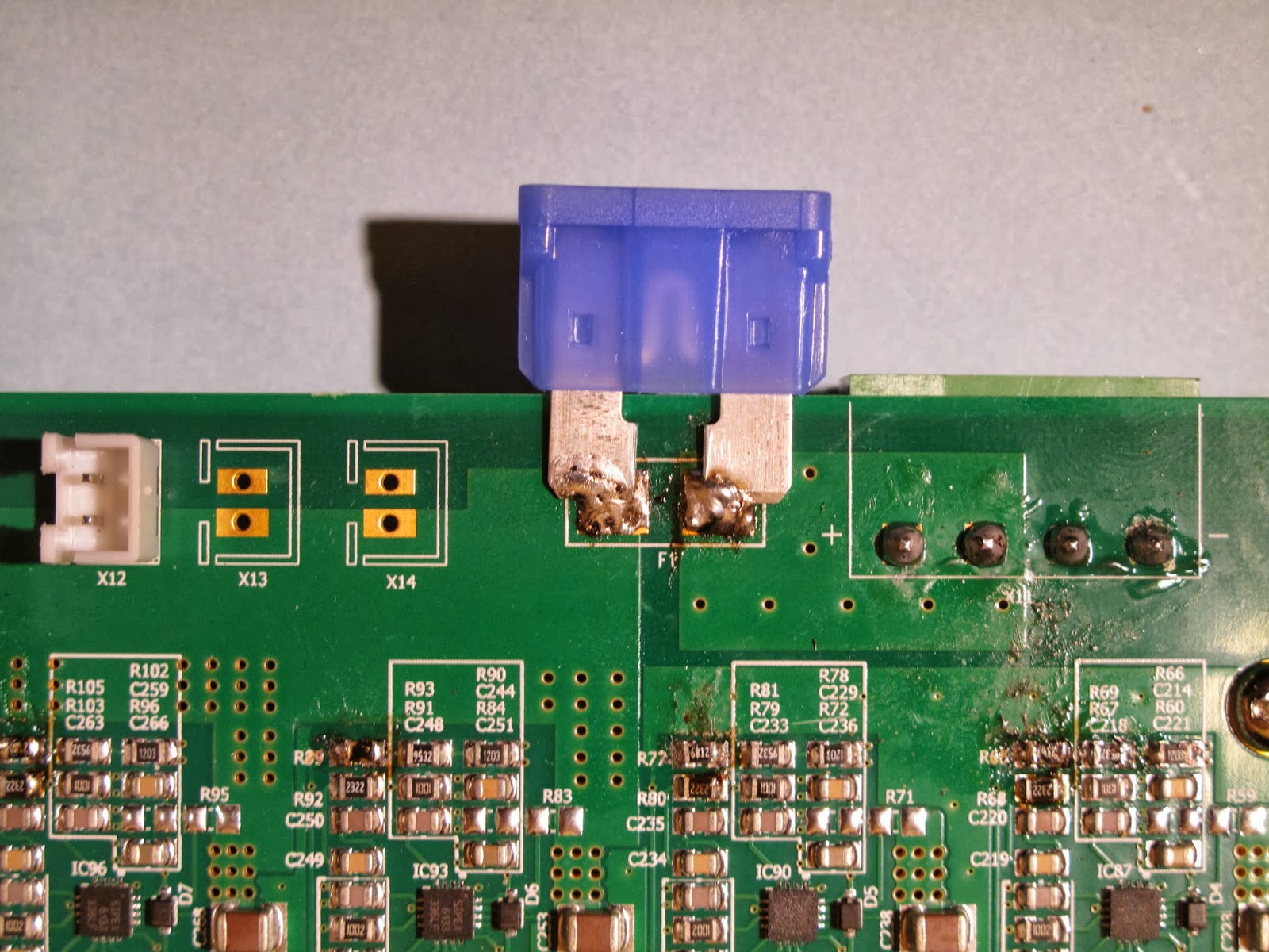 |
| 15A Blade fuse installed |
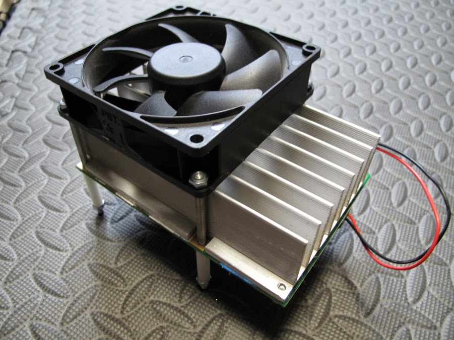
Be sure to triple check your work under magnification before powering up the device. Once everything has been triple checked go ahead and power up the device and check the console. If the efficiency begins to drop after a few minutes, the blade is not getting enough air flow. You will want to have fans directly blowing onto the heatsink or if you are in a backplane configuration, make sure you have over 85CFM pushing between the blades. Maybe consider a fan like this if heat becomes an issue.
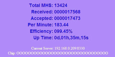 |
| Successfully Overclocked Blade Running at 13.4GH |
 |
| A Group of 5 Overclocked Blades |
Overclocking Kit Availability
 |
The ASICMiner Blade Block Erupter 13.4GH Overclock Kit
is available for purchase on eBay or you can contact me directly
If you are interested in experimenting with even higher clock speeds, I have a kit available with two different oscillators and resistor packs. Apply the same general idea outlined in this tutorial, but using higher speed components. Results are hit and miss and these modifications will require chip side cooling and a lot of air. The kit is available if you click on the image below.
 |
I bought one of your kits on eBay. It worked great! Thanks for putting this together.
ReplyDeleteGlad to hear it worked out Jeff. Thanks for letting me know.
DeleteThinking Man, I just want to say thank you. Installation was quick and breezy.. The less the downtime the more money i make. You have a GREAT tutorial on how to install and things needed. I was able to go straight to the local (insert witty local location that carries parts here, like wal-mart) and get everything i needed. The layout was straight forward with exact things to do which helped when removing the single heatsink screw helps get to that last solder point (or first, whichever side you started on).
ReplyDeleteMy next adventure is to put at least a 1200 watt grid tie system in my house. Help out with costs of the wifes curling iron and her rollers (or whatever else these women use to look even more astonishing throughout the day). This way she cant really complain the electric bill is rising slightly. Thanks again sir. P.S. Your customer service should be something of legend. WAY better then those over seas ones. lol. :-).
ReplyDeleteDavid, thank you for the kind words. Much appreciated!
ReplyDeleteAnytime sir. Thank you.
Delete